Publish date
Jan 12, 2024


By the time a part is ready for holes, you have invested significant labour, material, spindle time, and engineering energy. You may also be running short on time and stock to make adjustments or recover from mishaps. That’s why the importance of meticulously prepping, starting, and finishing holes can’t be emphasized enough.
Another consideration at this critical stage of production is that bores in a part often require another part to mate perfectly with them or travel cleanly through the hole. These requirements demand that sizing, straightness, concentricity, and finish are all to specification.
Manufacturers often get stuck somewhere in the boring phase of a job. In addition to their cutting challenges, they have real concerns about profitability, on-time delivery, customer relationships, and how problems from a production stalemate may trickle down to other scheduled jobs and resources.
Questions about fine boring typically fall into four categories:
Let’s discuss each issue, its unique challenges, and a few tips and tricks for producing a fine bore.
INCONSISTENT HOLE SIZE
When a fine boring job is set up, the plan typically involves leaving a certain amount of stock, say .020 inch, on the diameter for passes with the finishing tool. Regardless of whether you measure and set the tooling for this cut in the spindle or on a presetter, the forces exerted on the tool while cutting will cause a certain amount of deflection, and the size you set offline is not going to be what you get in-cut.

A frequent response is to use a preparation cut as a test cut, setting the tool undersize by 0.003 in. or 0.004 in., measuring the bore, and adjusting for the final cut. But this essentially leads into a spring pass. You are not going to have the same cutting forces from the first to the second cut.
It is recommended that you keep the stock allowance consistent from measuring cut to final cut. If you are leaving 0.020 in., remove 0.010 in. with the first pass, measure, adjust, and then finish. You will achieve much more consistent results.
Another common factor that contributes to non-repeatable hole sizes is tool change inconsistency—how accurately or repeatedly the tool is going in and out of the spindle. A first suggestion is to pay close attention to your toolholders. If you are investing in a fine-boring operation and/or new tooling, do not use toolholders that have been sitting around the shop for years. Without fail, they will create problems with repeatability.
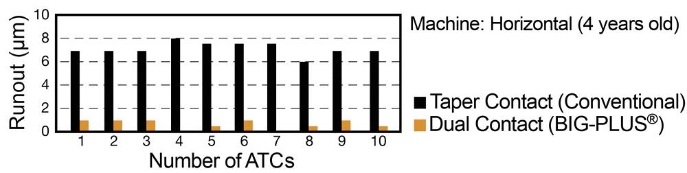
Spindle interface is also important to achieving consistent holes. Steep taper design—CAT or BT tools—drives the market, and nowadays many of those are BIG-PLUS® ground. This kind of dual-contact interface is highly recommended. In automatic tool change tests on a horizontal machining center, a dual-contact interface consistently demonstrates 5 to 6 microns less runout than taper-only contact interface.
And, yes, even little pull studs make a big difference. Wear and dimple marks on the body hinder repeatability. A 10th or 20th at the spindle nose of a tool that is sticking out 8 to 10 in. can cause severe runout at the cutting edge.
SURFACE FINISH
Several things can disrupt a bore’s surface finish; so here are a few of the most common causes.
TAPERED BORES
Tapered bores are generally caused by the cutting edge breaking down as it progresses through the bore. Reducing heat and/or the amount of time inserts are in the cut is a good way to combat tapered profiles, which usually means adjusting feeds and speeds. If it is an option, try increasing the feed rate to limit the time in the cut or reducing cutting speeds to lower temperatures. There are various ways to do this. For example, in materials that can work-harden you may need to increase speeds to direct the heat to the chip and away from the workpiece.
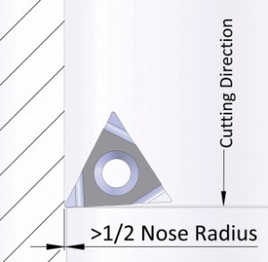
If that doesn’t work, look at the insert itself. If you are using a long-reach tool, try a standard chipbreaker design with a small radius that allows you to take lighter cuts. If that doesn’t provide good chip control, you can try switching to an insert with a more formed chipbreaker geometry. There are also specially ground inserts. If it’s a particularly rigid application, you may want to change the switch insert type completely and use something like an insert with an 80-degree corner.
HOLE ROUNDNESS
As we all know, achieving perfect roundness is easier said than done and that the common practice of interpolating with an older machine is a big task. A frequent mistake is assuming that a single-point finishing tool will round out the bore. Truth is, these tools aren’t built to address the non-roundness issue. They will likely help, but achieving perfect roundness with them is unlikely.
To remedy non-roundness, try using twin cutting boring heads for prep cuts. The opposing cutting forces guarantee a round hole so the finish tool has a consistent amount of stock to work with all the way around. Tooling balance is crucial to making a perfect circle, especially in high-speed or long-reach applications. Choose tools with balance compensation. The various of styles available include tools that balance automatically with built-in pinions and those that adjust with a scale ring on the back side.
Similarly, pay attention to part uniformity. If part of the bore lies along a very thin wall, it can deform during cutting. In cases like this, try to reduce the DOC of cut and take as little stock as possible on the finishing pass. In turn, you’ll need to remove more stock in your previous operation. You can also try changing to a ground insert that requires less cutting force.
Also, measuring holes while the part is still clamped can help to ensure the fixturing isn’t deforming the part. Don’t wait for the CMM to find out that a hole is out of round and then have to diagnose the issue. Admittedly, this isn’t always the easiest considering fixture investments, but it will pay off in the long run.
Did you find this interesting or helpful? Let us know what you think by adding your comments or questions below.
Very interesting and perfect 💪 for me
Boye Frederick
Sun, 08/22/2021 - 00:17