Publish date
Jan 22, 2024

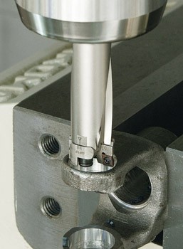
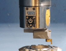
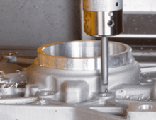
Before we get to some handy advice for using our newest boring solution, let’s run down the details of just what the MW Boring Head is. Adjustable insert holders with indexable inserts affix to a straight shank body to cover a diameter range not previously available from BIG Kaiser, permitting rough boring in small holes of Ø16mm-21mm (Ø630”-.827”). This new release is ideal for semi-finish boring operations of workpieces with die cast holes.
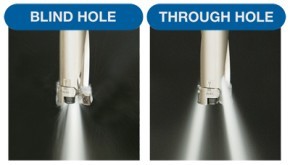
Efficient chip evacuation was a major consideration in the design of this tool. A spiral groove carved in to the body facilitates clean and quick chip removal with the help of coolant holes near the end of the groove. However, for blind-hole situations, an additional center-through coolant option was added to aid in chip evacuation for this tricky scenario. Simple stop screws makes choosing coolant preferences fast and easy.
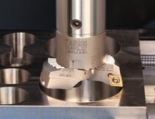
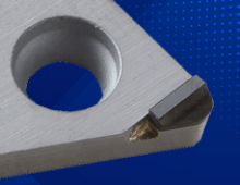
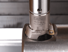
The two opposing die-steel insert holders feature a precision serrated mounting system, providing a secure and rigid connection similar to the KAISER 319 SW series. The insert holders are conveniently marked with a scale for coarse setting, and the radial adjustment screw allows for fine-tuning thanks to their .008” pitch. Coated inserts are available for common materials like steels (including stainless), ferrous materials such as ductile and cast iron, as well as non-ferrous materials like aluminum.
Tips from the Experts
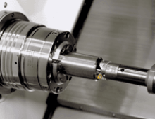
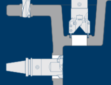
#1 Unlike other boring tools from BIG Kaiser, the new MW does not feature the modular KAISER KA/KAB connection. With its Ø20mm straight shank, the product performs best when paired with a milling chuck at fixed bore depths up to 4xd.
#2 Use center-through coolant when possible, especially in blind holes to aid chip evacuation, and if using external coolant supply, the cutting speed needs to be reduced.
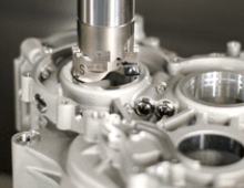
#3 In blind-hole applications, chips could gather at the hole bottom and cause the breakage of inserts or other parts, so pay close attention to this, especially in VMC applications.
#4 If there is not enough space at the hole bottom, make multiple passes after removing chips in between.
For detailed specs, cutting parameters and more images, click here to view the full product brochure.


Did you find this interesting or helpful? Let us know what you think by adding your comments or questions below.